The construction
Cause of the small inner measuments I decided to build the lamp head in a sandwich construction. The problem is to achieve a good thermal managment in order to get rid of the great amount of heat the four emitters are producing. This heat has to be tranfered quickly towards the housing. All LED have in comon to become less effective with higher temperatures so a good cooling is essential when building LED lights. The led manufactures still gives the efficiency numbers at 25 degree celsius (room temperature). But it is nearly impossible to reach this this theoretical temperatures cause high power leds tend to get hot when they are switched on for a while. The best you can do is to cool them down as good as it is possible. The better you do the more light you will have. As divers we have luckily one of the best cooling systems availible - water. Our job is the leed the heat as quick as possible into the water. So an aluminium housing is essential when building good led lamps and especially this high power gear. Plastic = shit.
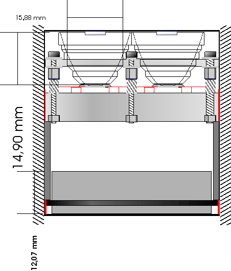
First of all lets have a look at the inner construction - klick to zoom
On this picture you can clearly see the three part construction of the light head - first part is the optical stage with its reflectors and the tiny glas optics on top of it. Followed by the emitter board and the electronic PCB on the bottom. The optical stage is fitted with screws to the thick emitter board and is held at distance with springs around the screws. Now you can adjust the distance of the reflector over the emitters carefully in order to get the best collimation. Between the emitter board and the electronic there are some spacers to fix it in the head and keep the right distance. The electronic is pressed onto the bottom with the emitter board in order to get a good thermal contact with the driver ICs on bottom of the PCB and the housing. That is important because the driver IC are getting hot over time and have to be cooled by the housing. The electronic itself is two sided with the higher components on top and the thinner ones on the other side. More about it later on.
The reflectors with optics
As mentioned before the optical stage consists of a combination of alu reflectors and optical gas lenses. The reflector do the main work directing the light strait above. But there is still a certain percent of light that goes out without contact to the reflector surface. In the middle of each led reflector there is a darker spot where only non reflected light goes out. You need a tiny PCX lens with the diameter of this black spot in order to focus this light into the hotspot that give it a small boost of around 20% brightness. The lenses are bonded with their flat side onto the main glas lens of the housing. The best for that is high quality transparent silicone - use it VERY, VERY thrifty.
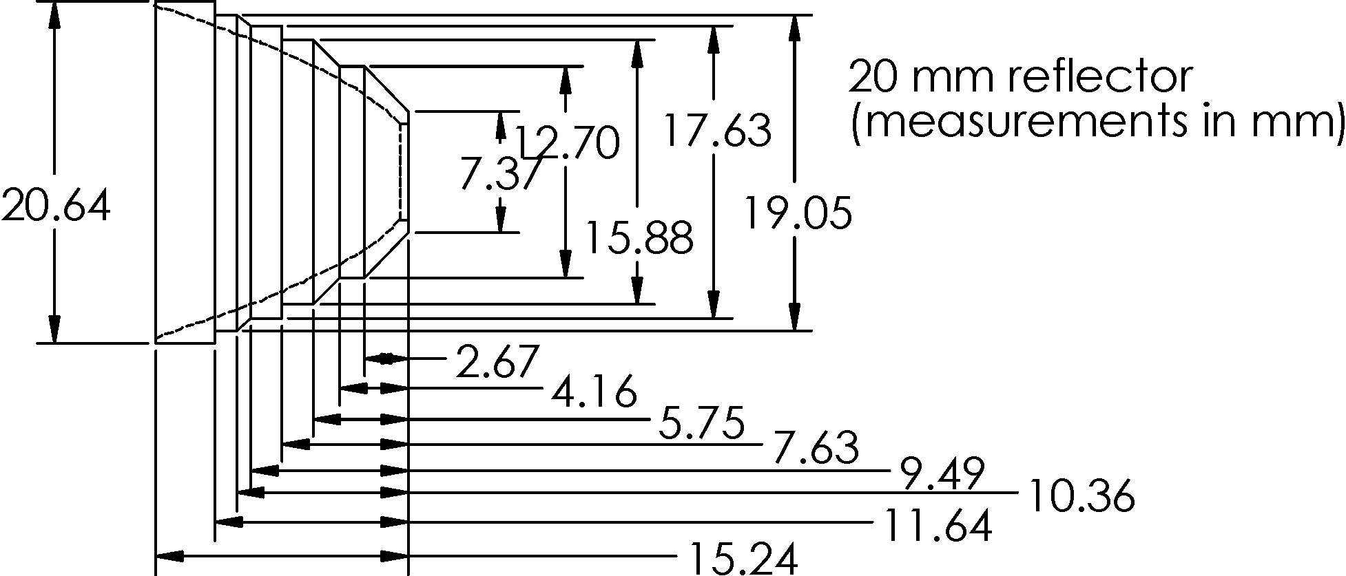
 The reflector are special led aluminium reflector with a coated surface and a orange peeling on it The photons are getting mixed a little bit because of that so you get a smooth transion form the hotspot to the sidespill without dark rings or so. You can get them from the shoppe. But it is possible to use other led reflectors with the right size like chromed ones build of plastic (less lightpower). The used McR-20J reflectors are designed to work with luxeon led. If they should work with an OSTAR you have to sand them down a little bit (around 0,8mm). Just do it carefully and test to find the best focal point. If you done it right there is only a small gap between the emitter surface and the reflector bottom so that every side photon can be directed to where it is needed.
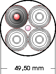
The four 20mm reflectors are fitted in an aluminium plate so that there is no gap between them (only in this case they will all fit in a 50mm diameter) Then you drill four holes for the holing screws into the alu plate.
 The optical lenses you need have to be choosen exactly regarding its diameter and focal length. With this 20mm reflector I took a 7mm lens. The focal length depends on the distance between the optical lens and the light emitting surface. It should be 1-2mm larger than this distance so that the focal point lies behind the emitter surface. In my case with a distance of 16mm I choosed a lens with 17mm focal length. If you take the exact distance as the focal length you get a direct image of the chip structures at the wall with 6 distinct lightpoints. By making the focal lenght a bit longer you get a slight blur and so a better light. Now bond them with the transparent silicone at the housing´s glas lens just in the middle of each relefector. Silicone has nearly the same optical properties like glas - but as said use only a little of that - just enough to build up a thin film underneath the lens. Here ist the stencil for the seat of the 20mm reflectors.
 The emitter board
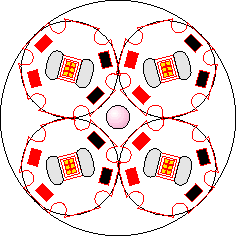
The heart of this lamp, the OSTAR emitters, are fitted on a 10mm thick aluminium plate and are screwed tightly with it. A little thermal compound between the board and the emitters is important for a good heat transfer. The bigger problem is to make the heat path from the alu board to the housing with very good heat disapation. You can do this with special thermal epoxy but then you have the disadvantage of no possible removing the board in case of problems. A better way is a high tec thermal silicon pad known from CPU to cooler connections. They have an outstanding thermal transfer factor and are coated on one side for adhesive bonding. You can get them for example from the german manufacturer Kunze (Typ KU-TXE 0,5mm). You need a pad with 10mm height and 160mm length. This special pad is able to hold the emitter board in place and is removable. Thanks to one plain surface it can be removed easly (look in the contrustion picture for the red lines). As a help you can download a Stencil. For best fit of the emitter board plus the thermal pad the board should be cut down around 0,9 mm under the housing diameter (50mm -> 49,1mm)
At least you drill the holes for the connection wires of the emitters and the holding screws - vóila you have a ready to use emitter board. A first test without housing cooling gives you a good impression what amount of heat is produced with this kind of emitters. For the connection wires I would recomment silicon encapsulated wires with a bounteous profile cause the wires have direct contact with the warm/hot emitter board and have to transfer up to 1A current. The more thick the wire the better is the restistance of that wire.
